Hello readers,
This is another one of those workarounds that I've been doing for a while and wasn't aware that a lot of people didn't know of it. Its a very quick method to creating depth in your elevations/sections without adding masses, using the linework tool, or utilising shadows. (although in Revit 2010, with directx turned on printing of views with shadows has improved exponentially!).
This is my first attempt at uploading a video so please let me know if people have any difficulties viewing. It has been encoded using the Techsmith codec. TSCC in AVI format.
Thursday, April 16, 2009


Thursday, March 26, 2009
Autodesk release 2010 Product Line Up
Autodesk today started shipping there 2010 product lineup.
http://store.autodesk.com/store/adsk/DisplayHomePage
Revit 2010 introduces:
New User Interface (ribbon) - which from my experience is a better implementation than most other platforms that have implemented the ribbon.
Conceptual Modelling tools - A complete redesign for the conceptual design modelling tools enabling nearly any form to now be modelled directly in Revit. You are no longer confined by blend, extrusion, sweep, revolve and swept blend. Instead simply draw the various components that would make the shape, select them and then hit create form/void... You still need to be aware of intersecting geometry as this will result in the "unable to create..." error that is typical in Revit. Furthermore with this tool you can apply complex patterns to them based on a UV breakup of the surface. And the very cool feature is this can all be controlled via the API to generate some amazing mathematically driven patterns for surfaces. Checkout Guy's blog for some examples shortly.
Performance Enhancements - 2010 ditches Open Gl for Direct 3D as well as being native x86/x64 with some minor multi-threading tasks now implemented (no longer two separate installs). Graphically 3D navigation is much faster that 2010 and should be a welcome addition for most offices. Also, anti-aliasing of 3D views means linework is going to be much smoother rather than stepped as well as being able to turn on gradient backgrounds for a little more effect to your perspective and orthogonal views.
Minor Drafting Tool inclusions - You can now control the underlay linetype on a system wide setting as well as halftones. Also a new tool called Spot Slope which can indicate the slope of a surface that its placed on (similar to a spot co-ordinate or spot elevation). Unfortunately it doesn't work with Ramps as they still require fixing... Be careful when tagging roof pitches in elevations to use your tab key as you may inadvertently tag the ridge line instead of the true perpendicular fall meaning you'll get a different value than expected.
Interoperability - Bi-directional communication with Civil 3D via the adsk format, the ability to import adsk files from Inventor for family creation (things like connectors are transferred as well as all the product information) - hopefully this will assist with some accurate content becoming available soon. Exporting to gbXML has also been improved with a full graphical review of the export and analysis now available prior to export to iron out any issues before hand.
Let downs:
http://store.autodesk.com/store/adsk/DisplayHomePage
Revit 2010 introduces:
New User Interface (ribbon) - which from my experience is a better implementation than most other platforms that have implemented the ribbon.
Conceptual Modelling tools - A complete redesign for the conceptual design modelling tools enabling nearly any form to now be modelled directly in Revit. You are no longer confined by blend, extrusion, sweep, revolve and swept blend. Instead simply draw the various components that would make the shape, select them and then hit create form/void... You still need to be aware of intersecting geometry as this will result in the "unable to create..." error that is typical in Revit. Furthermore with this tool you can apply complex patterns to them based on a UV breakup of the surface. And the very cool feature is this can all be controlled via the API to generate some amazing mathematically driven patterns for surfaces. Checkout Guy's blog for some examples shortly.
Performance Enhancements - 2010 ditches Open Gl for Direct 3D as well as being native x86/x64 with some minor multi-threading tasks now implemented (no longer two separate installs). Graphically 3D navigation is much faster that 2010 and should be a welcome addition for most offices. Also, anti-aliasing of 3D views means linework is going to be much smoother rather than stepped as well as being able to turn on gradient backgrounds for a little more effect to your perspective and orthogonal views.
Minor Drafting Tool inclusions - You can now control the underlay linetype on a system wide setting as well as halftones. Also a new tool called Spot Slope which can indicate the slope of a surface that its placed on (similar to a spot co-ordinate or spot elevation). Unfortunately it doesn't work with Ramps as they still require fixing... Be careful when tagging roof pitches in elevations to use your tab key as you may inadvertently tag the ridge line instead of the true perpendicular fall meaning you'll get a different value than expected.
Interoperability - Bi-directional communication with Civil 3D via the adsk format, the ability to import adsk files from Inventor for family creation (things like connectors are transferred as well as all the product information) - hopefully this will assist with some accurate content becoming available soon. Exporting to gbXML has also been improved with a full graphical review of the export and analysis now available prior to export to iron out any issues before hand.
Let downs:
- There are most likely going to be a number of bugs in the initial release so it may be worth waiting for WU1.
- No notable bug fixes.
- Not many drafting tool enhancements and no text enhancements.
- Great release for those doing landmark buildings, others may find the release light on features...
Thursday, March 05, 2009
Building Information Modelling Asia 2009
I've recently returned from a conference on BIM in Singapore. Apart from an injury I received on the flight home I considered it to be a very worthwhile event.
There were key speakers from Developers, representatives of BuildingSMART, Tekla, Autodesk, Gehry Technologies as well as numerous others.
I guess the biggest thing I got out of it was that Revit isn't the centre of the universe! BIM can still work equally as well even if a number of the disciplines are using difference platforms. Yes if everyone is utilising the same platform such as Revit it can somewhat automate some of the more mundane co-ordination tasks - but it is not pivotal to a successful BIM. There were quite a few quoin phrases thrown about such as "Big BIM", "Little BIM" and "Integrated Project Delivery (IPD)" but only the latter had any real significance. Big BIM and Little BIM seemed to me to be a cop out to being able to say "this was a complete BIM project" when BIM was only partly implemented.
IPD refers to the involvement of all the Owners, consultants and Architects right at the conception of the BIM to establish project deliverables, specific outcomes and results to ensure the project is developed in such a way as to automate and produce these outcomes with minimal effort. It also involves the entire team communicating at equal levels in a Project Documentation/Design/Analysis Utopia all operating for the sole purpose of whatever will best benefit the project. Rather than, "its not my job"...
Over the next few weeks I plan to compile and develop a spreadsheet of BIM capable software for all stages of a building lifcycle including FM, that identifies the best way's for each of them to communicate with each other with regards to file types, formatting and setup for various uses that maximises data integrity through the life of the project. I welcome people to post their findings and designs for best interoperability methods with the various other packages as well as most applicable software to co-ordinate it all. Personally, we are going down the Navisworks road...
If anyone also has any questions specifically about the conference please ask as I will be more than happy to elaborate on any of the subjects if people are interested.
There were key speakers from Developers, representatives of BuildingSMART, Tekla, Autodesk, Gehry Technologies as well as numerous others.
I guess the biggest thing I got out of it was that Revit isn't the centre of the universe! BIM can still work equally as well even if a number of the disciplines are using difference platforms. Yes if everyone is utilising the same platform such as Revit it can somewhat automate some of the more mundane co-ordination tasks - but it is not pivotal to a successful BIM. There were quite a few quoin phrases thrown about such as "Big BIM", "Little BIM" and "Integrated Project Delivery (IPD)" but only the latter had any real significance. Big BIM and Little BIM seemed to me to be a cop out to being able to say "this was a complete BIM project" when BIM was only partly implemented.
IPD refers to the involvement of all the Owners, consultants and Architects right at the conception of the BIM to establish project deliverables, specific outcomes and results to ensure the project is developed in such a way as to automate and produce these outcomes with minimal effort. It also involves the entire team communicating at equal levels in a Project Documentation/Design/Analysis Utopia all operating for the sole purpose of whatever will best benefit the project. Rather than, "its not my job"...
Over the next few weeks I plan to compile and develop a spreadsheet of BIM capable software for all stages of a building lifcycle including FM, that identifies the best way's for each of them to communicate with each other with regards to file types, formatting and setup for various uses that maximises data integrity through the life of the project. I welcome people to post their findings and designs for best interoperability methods with the various other packages as well as most applicable software to co-ordinate it all. Personally, we are going down the Navisworks road...
If anyone also has any questions specifically about the conference please ask as I will be more than happy to elaborate on any of the subjects if people are interested.
Thursday, July 10, 2008
Revit Rendering Fundamentals
Here is a link to the other presentation I did:
Apologies this file is rather large due to all the embedded images (37MB approx.)
Again, I love to hear feedback both good and bad. It gives me incentive to keep updating this page...
EDIT: Webserver no longer allows me to have files this large. Please see link to PDF.
Apologies this file is rather large due to all the embedded images (37MB approx.)
Again, I love to hear feedback both good and bad. It gives me incentive to keep updating this page...
EDIT: Webserver no longer allows me to have files this large. Please see link to PDF.
Friday, July 04, 2008
Families the Basics - including management
Well its about time I updated my blog. For those that couldn't attend the recent Revit Technology Conference I thought I would post links to my powerpoints should you wish to check them out.
This is the talk I did about Families.
Generally it investigates how to setup standards in your office in order to maintain control of your library and develop consistency as well as maximum functionality.
Unfortunately our webserver no longer allows me to post these large files. Please use this link to PDF.
It then looks at some of the basics of family creation of which I then did some live demo's. If enough people post interest, I'll upload a video screen capture of this... :-)
This is the talk I did about Families.
Generally it investigates how to setup standards in your office in order to maintain control of your library and develop consistency as well as maximum functionality.
Unfortunately our webserver no longer allows me to post these large files. Please use this link to PDF.
It then looks at some of the basics of family creation of which I then did some live demo's. If enough people post interest, I'll upload a video screen capture of this... :-)
Friday, May 30, 2008
Revit Technology Conference 2008
Its that time of year again!
Revit Technology Conference 2008 is on in June. I will be speaking as well as a host of other people. I strongly recommend you attend as its going to be 3 full on days of intensive training.
Hope you can make it.
Info can be found here http://www.rugsyd.com.au/rtc2008/rtc2008_events.htm
Revit Technology Conference 2008 is on in June. I will be speaking as well as a host of other people. I strongly recommend you attend as its going to be 3 full on days of intensive training.
Hope you can make it.
Info can be found here http://www.rugsyd.com.au/rtc2008/rtc2008_events.htm
Wednesday, February 20, 2008
Join Geometry Secrets
This is an interesting little trick that I've taken for granted for some time now and didn't realise a lot of people weren't aware of it.
If two adjacent walls are within say 25mm of each other and you use join geometry between the two walls (they don't even need to touch) the two walls inherit the openings of the other.
This is very handy when you are forced to model finish layers separetly in some situations. Saves you doing the unthinkable and using the evil "edit profile" option...
HTH.
If two adjacent walls are within say 25mm of each other and you use join geometry between the two walls (they don't even need to touch) the two walls inherit the openings of the other.
This is very handy when you are forced to model finish layers separetly in some situations. Saves you doing the unthinkable and using the evil "edit profile" option...
HTH.
Thursday, December 06, 2007
In Place families when should I use these?
In place families trip up a lot of new revit users. Sometimes its just so quick & easy to create a family on the fly in the project.
Unfortunately though they have some real negatives. For instance they typical have a big hit on your file size especially when you start making them reference surrounding geometry in the project. Also, one of the worst things you can do in Revit is start copying around the in-place families in the project...
Many new users don't realise that unlike a normal family all the copies are actually completely new families. That is, changing one, will NOT update all the others. If it repeats it needs to be an external family.
So what in-place families do I create?
Generally the only things I'll model in place occassionally are floors, stairs & ramps. Modelling monolithic stairs and ramps as floors is a great idea as you can then attach walls to them and get those connections to floors correct. This is also because of the current limitations of the stairs & ramps.
I prefer to model complex floors as in-place purely because they don't adjust when you move walls, causing sketches to occassionaly become invalid and delete your floor. This also gives you absolute control over footings, and various beams through the slab.

Another trick is with High-Rise buildings where you have complex floors that are typical over a number of levels.
- I'll model the first one in-place,
- Then whilst still in edit family mode, copy all the geometry and paste aligned into a new external generic model family and save it as say "Floors 3-9".
- I then switch back to the project and delete the inplace family i just made.
- I create a new in-place Floor family called "Level 3 Floor" and load the generic model family "Floors 3-9" into it and place it on level 3.
- Then finish the family.
- Revit then understands that this family is a floor allowing you to attach walls to it.
- You can then copy and paste by level to levels 4-9 and rename in the inplace families as per the level they are apply to. Yes we did just copy and inplace family, but because its contents is purely an external family there is no real overhead in doing this. Plus if we make a change to that generic model and reload it, it will update all of our floors!
Let me know if you'd like me to post any other examples...
Revit Referencing Sheets on View Tags
Do you use the Referencing Sheets parameter in your view tags?
If you do then I bet you've had times when you thought why on earth is Revit choosing to reference from some bizarre view instead of the one you want.
Well its really quite simple -
It uses the drawing sheet numbers to determine which view to back reference.
For instance, lets say you have a sheet set as per the following:
010 Site Plan
020 Existing Plan
030 Demolition Plan
040 General Arrangement Plan
050 Elevations
060 Sections
etc.
Now lets say you have your section and elevation markers turned on in all those views and they haven't had the "hide at scales coarser than" parameter assigned properly.
In this case your Elevations & sections would display their referencing sheet as 010. This is because when you are looking through the set its the first drawing you would come to (logical hey).
Now if we go to the Site Plan and turn off the sections/elevations or charge our "hide at scales coarser than" parameter so as to effectively turn them off in this view. Our sections and elevations are now magically updated to reference back to 030 (this is assuming that they are new construction phase sections and elevations). Again because its the first drawing you would see the markers when looking through the set.
If you're anything like me, I want mine to back reference to the General Arrangement Plan (040). So our dilemma is do we turn off the section & elevation markers in this view? (probably the obvious choice) or the alternative and probable wrong solution would be to adjust our set order so the general arrangement plan comes before the demolition plan in the set...
I look forward to a setting in Revit where we can override this behaviour in special instances. But understanding this may help you identify why sometimes a view is being referenced from a strange place.
----------
I've also noticed some strange circumstances, usually when dependant views are involved where views reference back to a sheet that has the markers turned off. Hopefully this bug will be fixed or maybe it was just related to my file being corrupt?
If you do then I bet you've had times when you thought why on earth is Revit choosing to reference from some bizarre view instead of the one you want.
Well its really quite simple -
It uses the drawing sheet numbers to determine which view to back reference.
For instance, lets say you have a sheet set as per the following:
010 Site Plan
020 Existing Plan
030 Demolition Plan
040 General Arrangement Plan
050 Elevations
060 Sections
etc.
Now lets say you have your section and elevation markers turned on in all those views and they haven't had the "hide at scales coarser than" parameter assigned properly.
In this case your Elevations & sections would display their referencing sheet as 010. This is because when you are looking through the set its the first drawing you would come to (logical hey).
Now if we go to the Site Plan and turn off the sections/elevations or charge our "hide at scales coarser than" parameter so as to effectively turn them off in this view. Our sections and elevations are now magically updated to reference back to 030 (this is assuming that they are new construction phase sections and elevations). Again because its the first drawing you would see the markers when looking through the set.
If you're anything like me, I want mine to back reference to the General Arrangement Plan (040). So our dilemma is do we turn off the section & elevation markers in this view? (probably the obvious choice) or the alternative and probable wrong solution would be to adjust our set order so the general arrangement plan comes before the demolition plan in the set...
I look forward to a setting in Revit where we can override this behaviour in special instances. But understanding this may help you identify why sometimes a view is being referenced from a strange place.
----------
I've also noticed some strange circumstances, usually when dependant views are involved where views reference back to a sheet that has the markers turned off. Hopefully this bug will be fixed or maybe it was just related to my file being corrupt?
Saturday, November 17, 2007
Mr Spot's 5 Golden Rules for Revit
I had an anonymous user request my 5 golden rules which I thought was a great idea!
The hard part is trying to prioritise what I think are my top 5 rules, so hard in fact that I think I need to break it down into 2 categories. Project & Family:
PROJECTS
The hard part is trying to prioritise what I think are my top 5 rules, so hard in fact that I think I need to break it down into 2 categories. Project & Family:
PROJECTS
- Work in multiple views. When you are working on your model make sure you completely understand the extents of what you are editing. I don't believe this can be done from any single orthogonal view. Working in 3D is great and should be done as much as possible as you can quickly see how the elements you are manipulating interact with elements around them (make use of section boxes to do this also). Too many times I see users trying to make changes only in a plan and then a week later discovering all the issues they have made for themselves in their sections...
- Setup your template effectively and continually update it & customise templates at the beginning of new projects to suit that project. If you find you have to make graphical changes to your project everytime you want to print something or once it reaches a certain stage then there is a good chance your template file isn't setup appropriately. The earlier you do this and the quicker you update your templates the less redundant work you'll have to do updating the many revit files you end up with.
- Plan your project! Sit down with pen and paper first, especially for large projects or projects of an unfamiliar type, and work out exactly how you are going to document it. Are you going to use groups or links or design options? If so what are the issues in doing this and how are you going to resolve these? How is the project team going to work? Important questions that need to be resolved as soon as possible, preferably before the model is started.
- Develop a system of control for your Library. Family naming conventions, parameters (what do I want to show up in my schedule?), displays at various scales...
- Make use of your model as much as possible for drafting and details. If you use your model as the basis for your details then you can identify issues before they get to site. Yes of course you should still draft over these for details, but using the model as the basis you know when your details need to be updated or re-looked at.
Hmm, most of these are standards based which shows my position as CAD/BIM Manager. But really having your standards and protocols in place is one of the MOST important tasks in maintaining an effective Revit working environment.
FAMILIES:
- Setup Reference planes first! I can't stress this enough. It makes creating parametric families so much simpler. Place them in and give them names and appropriate strengths (ie: Centre Front/Back, Bottom or Weak)
- Give your family an appropriate ORIGIN point. This is especially important when using arrays as I've spoken about previously.
- Do all families as non-hosted (there are some exceptions) first. Then simply nest them into the hosted template. This way its very simple to constrain them to their host.
- Fill out and add parameters & types for all your families. As a good friend of mine says, Wesley Benn, leverage as much data as possible. Info entered once here is info that doesn't need to be entered 10 times in your next 10 projects...
- Minimise numbers of families by making them as flexible as possible. Less families means, smaller project sizes, quicker load times, less things to change and things are easier to find. Refer to some of my previous posts to see some methods of doing this.
Well that's my list. I'm sure I could easily have a top 100...
As always your comments are most welcomed.
Thursday, November 15, 2007
Requests for Posts
Hi everyone!
Please post your comments on this thread as to any particular items you would like me to touch on.
I've finished uni now and have the internet on at home again so should be able to start posting more frequently...
I'll then try to add posts based on peoples requests...
Cheers!
Please post your comments on this thread as to any particular items you would like me to touch on.
I've finished uni now and have the internet on at home again so should be able to start posting more frequently...
I'll then try to add posts based on peoples requests...
Cheers!
Wednesday, October 24, 2007
3D Engraved Model Text
I had someone request this the other day and the solution is really very simple.
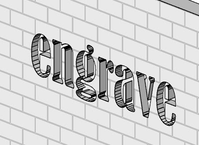
Simply create your model text as you would normally and set the plane so the text is embedded on the face of the wall or system family that you want to engrave the text on.
Use your join geometry tool on the wall and the model text - This makes revit cutout the model text from the wall.
Now just set the material of your model text to have a 100% transparency...
Too Easy!!
Tuesday, September 11, 2007
A "Family Type" Parameter for swappable subcomponents
I'm sure a lot of you have seen this before and its a really powerful tool. I'm referring of course to the ability to have "Family Type" parameters in a family for nested sub components.
What does that mean?
It means you have a single door where you can swap out the panel, or handles or frame. This avoids you having many different door families to achieve the same thing. It also means you don't have to load in 15 different families into your project, instead you may only need 2 or 3 and thus its better for file size.
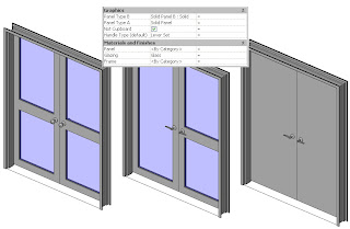
Flexibility is a great thing.
So how do you make one of these parameters?
Well the key thing to having this work correctly is that all the sub-components that you wish to swap out must have the same insertion/origin point and be constrained by that point.
Begin with a template:
Start with a "non-hosted" generic model family template (remember you can always change the family category later).
Now we need to set the "defines origin" reference planes in the X, Y and Z planes.
My template for door panels is setup as follows:
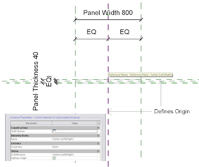
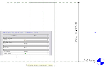
So my defining origin points are the Bottom Reference Plane (note I set it to be "Is Reference = Bottom), Centre Left/Right & Centre Front/Back.
Make note of this as when you load this panel into your project you need to define it by these points.
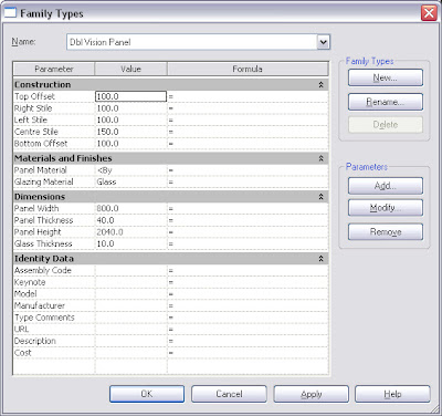
These are the parameters I include in the door. Note I have parameters to control vision panels if they exist. This way I have even more flexibility...
So once you've finished you need to load your panels into the host door family.
NOTE: This is personal preference, but I leave my door panels as generic models and set my door hardware to Furniture category.
DO NOT load lots and lots of door types into the one family. If you load too many your family will become too large and take ages every time you want to make a change to it. Load your standard door panels (most commonly used) only. I then have a subfolder that has an extensive library of door panels & hardware that I only load in on a per project basis...
Now we need to setup the host family.
Start with the Door Template. As a general rule I always delete the existing trim extrusions and remove their associated parameters. The other change I make is to the Width & Height parameters. In the template the height and width parameters are actually associated to the opening... I don't like this, I prefer to use the "Rough Height & Rough Width" parmeters for the opening sizes and then use the Width and Height Parameters for the panel sizes. So change this if you agree with my logic (just select the Width dimension and change it to Rough Width in your options bar pull down)
The next thing I'll do is load the panels that I want in the door family.
Upon doing this I immediately link through the parameters for every door type I loaded...

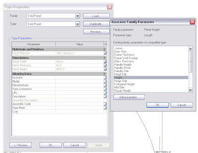 This is the labourious part. Go to each type you loaded in the project browser, go to the element properties for each one, then link through all the parameters by clicking the "link" column for each parameter. For the first one you will need to use "Add Parameter..." for the ones that don't exist yet. Then after this you can just pick them. Note I link Panel Width & Panel Height to Width & Height respectively. (note for double doors I don't do this because I have extra parameters for each door panel, left/right).
I then go to plan view and place one of the door panels randomly. I then constrain its left/right location using its centre left/right origin point (use the align tool and then lock it). I then constrain its front back location using its Centre front/Back origin point.
I generally have an undercut parameter so to constrain the Door in the Z axis I go to element properties and in the instance parameters I'll link the level offset parameter to my undercut parameter...
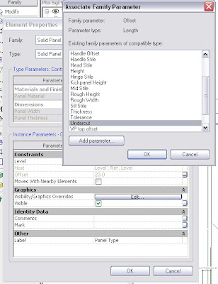
So we've now constrained the panel in the X, Y & Z axes which was the insertion point of the panel.
Now we need to add the Family Type parameter to enable us to swap out the panel for the other loaded panels...
Select the panel you placed. Look at your options bar
 You see there is drop down called label and its currently set to "None". Select "Add Parameter", give it a name and your done.
If you load this door into a project you now have a parameter that enables you to swap out the panels as needed.
Now this quick tutorial didn't really go into the depth of creating a door it was more to concentrate on the parts that are required to successfully create a working "Family Type" parameter.
I hope someone finds this useful.
Post if you have queries, as I'll add more detailed info if it proves people still have trouble.
Cheers.
Curtain Wall - Corner Cutouts
If you've ever tried using embedded curtain walls for strip glazing then I'm sure you've seen this situation at the corners...

That's right, the corner doesn't get cutout correctly...
Now, there are a few different ways to resolve this. My preference is to create a wall hosted generic model. Then I just create a void in that family, give it instance parameters for width, height, thickness etc... And finally use the cut geometry tool to tell the void to cut the host.
Now I can just load that family into my project place it in the offending wall, use the grips to adjust its size to fit the situation and then move it into place.

Too easy. Advantages? Well its a family so they can easily be filtered, they don't have a huge effect to your file size and its easy to adjust. Plus you can always select them and change them as needed.
For one I prepared earlier use this link:
http://www.cadway.com.au/Signatures/CLP/Corner_Cutout.rfa
I hope you find this helpful :)
Tuesday, August 28, 2007
Revit Technology Conference 2007
Hey Reviteers,
I hope those of you who have been to the RTC07 roadshow have found at least some of it beneficial?
Feel free to post your comments...
I've just got back from the Auckland Conference which went very well apart from a minor hardware glitch on one of the laptops (the video card kicked the bucket during a hot swap). On a whole and from speaking to a few of the attendees I feel it is running well and people are getting something out of it.
I've learned a couple of nifty little tricks myself! I especially liked Chris Needham's awakening of the Scope boxes which I've never really used. I had no idea they had that many uses.
During the roadshow I've had a couple of requests for tutorials/families to be uploaded.
So far they have been the "generic wall hosted opening I use for curtain wall strip glazing to cleanup the corners" and "a step by step tutorial on how to create families with swappable components".
Both of these I'll upload in the next two weeks or so. Hold me to that, if you don't see it in that time frame add your comments and abuse me and hopefully that will kick me into gear.
Its been great putting faces to so many of the people that have found my online contributions beneficial over the years.
Cheers.
I hope those of you who have been to the RTC07 roadshow have found at least some of it beneficial?
Feel free to post your comments...
I've just got back from the Auckland Conference which went very well apart from a minor hardware glitch on one of the laptops (the video card kicked the bucket during a hot swap). On a whole and from speaking to a few of the attendees I feel it is running well and people are getting something out of it.
I've learned a couple of nifty little tricks myself! I especially liked Chris Needham's awakening of the Scope boxes which I've never really used. I had no idea they had that many uses.
During the roadshow I've had a couple of requests for tutorials/families to be uploaded.
So far they have been the "generic wall hosted opening I use for curtain wall strip glazing to cleanup the corners" and "a step by step tutorial on how to create families with swappable components".
Both of these I'll upload in the next two weeks or so. Hold me to that, if you don't see it in that time frame add your comments and abuse me and hopefully that will kick me into gear.
Its been great putting faces to so many of the people that have found my online contributions beneficial over the years.
Cheers.
Tuesday, April 24, 2007
Revit 2008 - Point edit Floor & Roof Tool
Finally we are able to create those complicated falls of roofs and floors that occur on nearly every project, natively in Revit.
So how powerful is this new tool? Can it do everything I want it to? What can't it do?
I'll try to answer these questions as best I can:
To save the new users the frustration of trying to do something that the tool can't yet create I'll list the shortfalls and bugs that currently exist in this fantastic new tool.
1. As it states in the Revit help, the new point edit tool cannot be used if the floor or roof sketch contains curved segments. This doesn't mean you can't have a curvy roof though :) You just have to create your roof with straight segments first and then use Modelling->Opening->Vertical Opening to cut the element to the desired shape.
2. Further extrapolating on the above functionality with curves. There are certain circumstances where the opening will NOT cut the element and instead reports an error "can't create geometry". I've experienced this once on a floor that had 85 point edits on it as well as multiple cuts to create a curved edge. The current workaround to this is to create smaller openings until you can identify the location that is causing the issue.
3. If you have two split lines very close together (say less than 2mm) you begin to get some strange occurences in sections. That is, the floor/roof will not get cut by a section OR section box for that matter. Instead the whole floor or roof displays similar to the behaviour of certain family categories such as furniture... In this case you are better use a single line and break it into segments.
4. You can only have 1 variable layer or all variable layers. That is, you can't have the top layer of your floor a variable thickness as well as the bottom layer having separate points and its own variable thickness. The solution being to use multiples floors and to join them together - it helps if you make them overlap so you don't get the can't join geometry error.
That about covers the issues i'm currently aware of. But hey, lets stop being so negative and look at what this new tool can do for us...
So far my office has made use of this tool for tiles with a topping slab with falls to floor wastes, also sidewalks or footpaths, variable thickness rigid insulation, and tapered floors that even include thickenings.
This is just some of the uses of the new tool, as you can see my uses have been primarily floors but i'm sure others have plenty of other uses for the tool (FEEL FREE TO POST YOUR USES).
So how does it work? (images to come later)
1. First you create your floor using straight lines only and finish sketch.
2. Now select your floor. You see 5 new options display in the element toolbar.
3. ...to be continued when I have some free time in the next week or so...
So how powerful is this new tool? Can it do everything I want it to? What can't it do?
I'll try to answer these questions as best I can:
To save the new users the frustration of trying to do something that the tool can't yet create I'll list the shortfalls and bugs that currently exist in this fantastic new tool.
1. As it states in the Revit help, the new point edit tool cannot be used if the floor or roof sketch contains curved segments. This doesn't mean you can't have a curvy roof though :) You just have to create your roof with straight segments first and then use Modelling->Opening->Vertical Opening to cut the element to the desired shape.
2. Further extrapolating on the above functionality with curves. There are certain circumstances where the opening will NOT cut the element and instead reports an error "can't create geometry". I've experienced this once on a floor that had 85 point edits on it as well as multiple cuts to create a curved edge. The current workaround to this is to create smaller openings until you can identify the location that is causing the issue.
3. If you have two split lines very close together (say less than 2mm) you begin to get some strange occurences in sections. That is, the floor/roof will not get cut by a section OR section box for that matter. Instead the whole floor or roof displays similar to the behaviour of certain family categories such as furniture... In this case you are better use a single line and break it into segments.
4. You can only have 1 variable layer or all variable layers. That is, you can't have the top layer of your floor a variable thickness as well as the bottom layer having separate points and its own variable thickness. The solution being to use multiples floors and to join them together - it helps if you make them overlap so you don't get the can't join geometry error.
That about covers the issues i'm currently aware of. But hey, lets stop being so negative and look at what this new tool can do for us...
So far my office has made use of this tool for tiles with a topping slab with falls to floor wastes, also sidewalks or footpaths, variable thickness rigid insulation, and tapered floors that even include thickenings.
This is just some of the uses of the new tool, as you can see my uses have been primarily floors but i'm sure others have plenty of other uses for the tool (FEEL FREE TO POST YOUR USES).
So how does it work? (images to come later)
1. First you create your floor using straight lines only and finish sketch.
2. Now select your floor. You see 5 new options display in the element toolbar.
3. ...to be continued when I have some free time in the next week or so...
Friday, October 20, 2006
Reloading Families of a different Name
Have you ever renamed a family and then wanted to load it back into a project without having to swap out your families of a different name and risk losing tags and dimensions?
Well its possible.
In your project browser (where all your sheets/views are list at the left of screen) scroll down to the families section and expand the list.
Now find the family you want to overwrite.
Right click and select reload.
Now navigate to the family you want to overwrite it with. Amazingly it doesn't need to be the same name or even the same family category
Once reloaded revit will swap out all your families of this type in the project for this new version.
This is good for keeping file sizes down and avoiding excess loaded families.
Hope this helps :)
Comments are welcome as always.
Well its possible.
In your project browser (where all your sheets/views are list at the left of screen) scroll down to the families section and expand the list.
Now find the family you want to overwrite.
Right click and select reload.
Now navigate to the family you want to overwrite it with. Amazingly it doesn't need to be the same name or even the same family category
Once reloaded revit will swap out all your families of this type in the project for this new version.
This is good for keeping file sizes down and avoiding excess loaded families.
Hope this helps :)
Comments are welcome as always.
Saturday, May 20, 2006
Export to DWG Known Issues
This is a compiled list of DWG export problems. Hopefully this list will see some of these issues ironed out in subsequent releases. If you have any further issues that you think should be listed or comments on how some of these issues have effected your productively please post them.
1. Elements that have used the linework tool on certain category families do not get exported.
2. When the linework tool is used on an underlay to show the roof and the underlay is turned off, in the resulting export the roof hatch is typically exported also...
3. White, no pattern fills created in annotation families or any family for that matter export to AutoCAD and print as solid black making the annotations unreadable. FIXED
4. Elements in sub-categories are not exported to their subcategories even though they have been mapped to a seperate layer in the export layers file. THIS ISSUE HAS BEEN RESOLVED WITH A LATER BUILD OF REVIT. ELEMENTS ARE STILL EXPORTED TO THEIR CATEGORY LAYER AS BLOCKS, HOWEVER PARTS OF THESE BLOCKS CAN BE TURNED OFF USING THE SUBCATEGORIES. FIXED
5. Crop Region translations when exporting sheets directly correspond to those in Revit. The issue being is that an AutoCAD viewport crops text and annotations where is Revits doesn't...
6. When Override host layers is enabled for walls etc, the resulting export places these lines using an unpredictable color which doesn't correspond with the export layers file. Typically Color 10 or Color 50 so these need to be assigned in your CTB file.
7. Dimension and text should create new styles upon export rather than using the STANDARD style as this creates issues with older versions of AutoCAD commonly used by clients and consultants.
8. When loaded generic models are used as an in-place floor when a callout of them is exported the entire floor comes across in the result export. This is an issue as if the setting is used to export out to a single sheet often this floor then overlaps the other details on the sheet making them appear incorrectly.
9. Linetype translations are still unpredictable. Often the linetypes used in revit don't translate through into the export. A solid line is the result. For instance overrides applied using a filter to select specific wall types to display in a particular manner.
10. The penultimate would be for an exported titleblock to export with attributes created for the parameters. Some of our clients have database systems they use for managing drawings (checking in and out etc) that link with these attributes. As the various consultants do not currently use Revit the only deliverables are DWG and DWF/PDF. As such these resultant exports need to be perfect and useable in order to work appropriately within a system such as this.
11. Text leaders somtimes get exported with an uncontrollable overridden color. Color 10 or Color 50...
Feel free to add comments
1. Elements that have used the linework tool on certain category families do not get exported.
2. When the linework tool is used on an underlay to show the roof and the underlay is turned off, in the resulting export the roof hatch is typically exported also...
3. White, no pattern fills created in annotation families or any family for that matter export to AutoCAD and print as solid black making the annotations unreadable. FIXED
4. Elements in sub-categories are not exported to their subcategories even though they have been mapped to a seperate layer in the export layers file. THIS ISSUE HAS BEEN RESOLVED WITH A LATER BUILD OF REVIT. ELEMENTS ARE STILL EXPORTED TO THEIR CATEGORY LAYER AS BLOCKS, HOWEVER PARTS OF THESE BLOCKS CAN BE TURNED OFF USING THE SUBCATEGORIES. FIXED
5. Crop Region translations when exporting sheets directly correspond to those in Revit. The issue being is that an AutoCAD viewport crops text and annotations where is Revits doesn't...
6. When Override host layers is enabled for walls etc, the resulting export places these lines using an unpredictable color which doesn't correspond with the export layers file. Typically Color 10 or Color 50 so these need to be assigned in your CTB file.
7. Dimension and text should create new styles upon export rather than using the STANDARD style as this creates issues with older versions of AutoCAD commonly used by clients and consultants.
8. When loaded generic models are used as an in-place floor when a callout of them is exported the entire floor comes across in the result export. This is an issue as if the setting is used to export out to a single sheet often this floor then overlaps the other details on the sheet making them appear incorrectly.
9. Linetype translations are still unpredictable. Often the linetypes used in revit don't translate through into the export. A solid line is the result. For instance overrides applied using a filter to select specific wall types to display in a particular manner.
10. The penultimate would be for an exported titleblock to export with attributes created for the parameters. Some of our clients have database systems they use for managing drawings (checking in and out etc) that link with these attributes. As the various consultants do not currently use Revit the only deliverables are DWG and DWF/PDF. As such these resultant exports need to be perfect and useable in order to work appropriately within a system such as this.
11. Text leaders somtimes get exported with an uncontrollable overridden color. Color 10 or Color 50...
Feel free to add comments
Tuesday, May 16, 2006
Revit 9 Filters Explained
Filters are a very powerful new tool available in Revit 9.
They give you the ability to control the visibility of any group of elements you define. Including their line colour, line style, and lineweight as well as whether that particular group of elements is visible.
They give the user the ability to control elements in way where previously mistreating worksets was the only method. Personally I still feel the need to control elements with worksets sometimes.
Before I begin with a quick tutorial, filters cannot be used on annotation elements such as section markers (unfortunately...)
Being by going to your visibility settings for the view you wish to add a filter.
Click on the filter tab.
Click Filters down the bottom.
Click New, to add a new filter.
Name it accordingly. Best to use something descriptive so you'll be able to use it again in another view at a later stage.
Select which element categories you'd like it to filter through... You can select multiple or single categories.
Select filter by... This enables you to filter from all the shared and project parameters available for these elements.
Then select the way you want to filter it (contains, equals etc)
Then type in the condition you require. (you can repeat this to set multiple conditions in a single filter)
Now insert this filter into the view.
Now all elements matching this criteria can be manipulated independently, either by turning them off, giving them a different line style (for example fire rated walls or structural walls...)
You can also access you filters through you settings menu.
They give you the ability to control the visibility of any group of elements you define. Including their line colour, line style, and lineweight as well as whether that particular group of elements is visible.
They give the user the ability to control elements in way where previously mistreating worksets was the only method. Personally I still feel the need to control elements with worksets sometimes.
Before I begin with a quick tutorial, filters cannot be used on annotation elements such as section markers (unfortunately...)
Being by going to your visibility settings for the view you wish to add a filter.
Click on the filter tab.
Click Filters down the bottom.
Click New, to add a new filter.
Name it accordingly. Best to use something descriptive so you'll be able to use it again in another view at a later stage.
Select which element categories you'd like it to filter through... You can select multiple or single categories.
Select filter by... This enables you to filter from all the shared and project parameters available for these elements.
Then select the way you want to filter it (contains, equals etc)
Then type in the condition you require. (you can repeat this to set multiple conditions in a single filter)
Now insert this filter into the view.
Now all elements matching this criteria can be manipulated independently, either by turning them off, giving them a different line style (for example fire rated walls or structural walls...)
You can also access you filters through you settings menu.
Wednesday, April 12, 2006
Object Styles Explained
Object styles are located both in the project and in families. Every family, system and annotation category has atleast one object style. They are used to control globally how an object is displayed with regards to lineweight, colour and type. These can be overridden per view or changed throughout a project either in your "visibility graphics controls" or your "settings->Object Styles" respectively.
In a family:
When you are in a family going to settings->Object Styles can create new subcategories for elements that will enable them to be turned off or their display manipulated without changing all elements in that category. For example:
Say we have a generic model family and we create a new object style by going to our object style settings, clicking NEW and selecting sub-category of generic models and name in "Signage". We could then select individual solid geometries located in our family and go to their properties and set their subcategory to "Signage". Now if we were to load this family into a project we could turn off signage in our visibility settings and it would just turn off these geometries whilst keeping on our other generic models.
The other items that are created when adding a new object style are new linetypes (this is where some people become confused as in families you do not create new linetypes you create new object styles). If we were to select symbolic lines in our family you'll note that two new linestyles are now selectable. That is, Signage (cut) and Signage (projection). Similarly lines drawn in this object style can be turned off or manipulated independant of all generic models as previously outlined.
In a project:
In Settings->Object Styles in a project we can change how a particular sub-category or category is displayed globally throughout the model by editing its properties. You'll note we have multiple tabs, for model, annotation etc for the different classes of elements.
These can also be overridden per view to enable exceptions to the graphical display of these elements for paricular views.
In a family:
When you are in a family going to settings->Object Styles can create new subcategories for elements that will enable them to be turned off or their display manipulated without changing all elements in that category. For example:
Say we have a generic model family and we create a new object style by going to our object style settings, clicking NEW and selecting sub-category of generic models and name in "Signage". We could then select individual solid geometries located in our family and go to their properties and set their subcategory to "Signage". Now if we were to load this family into a project we could turn off signage in our visibility settings and it would just turn off these geometries whilst keeping on our other generic models.
The other items that are created when adding a new object style are new linetypes (this is where some people become confused as in families you do not create new linetypes you create new object styles). If we were to select symbolic lines in our family you'll note that two new linestyles are now selectable. That is, Signage (cut) and Signage (projection). Similarly lines drawn in this object style can be turned off or manipulated independant of all generic models as previously outlined.
In a project:
In Settings->Object Styles in a project we can change how a particular sub-category or category is displayed globally throughout the model by editing its properties. You'll note we have multiple tabs, for model, annotation etc for the different classes of elements.
These can also be overridden per view to enable exceptions to the graphical display of these elements for paricular views.
Subscribe to:
Posts (Atom)