Xrev API Tools: Increase Productivity!

Feeds

Loading...
Showing posts with label Revit. Show all posts

Wednesday, September 09, 2015

Revit Railings - Long Standing Issues

I'm sure I'm not the only one he gets frustrated by the Railing tools in Revit.  I thought I'd put together this post to point out the type of day to day frustrations they cause and what I'd like to see implemented to solve the problem.

Extensions and Terminations


Here it can be seen a 180° railing termination and a standard 300mm extension.
 
As you can see, dimensionally its accurate.
 
But look at the Length I had to give to achieve this?
As you can see that dimension doesn't seem to correlate to anything?
  • I've checked the Termination family and its origin is set as the Centre Left/Right Reference Plane which is located exactly where the 300mm dimension is, and the Extension Length is set to 0, as I don't want it to be subtracted from the Extension Length.  IE: It should be 300mm and then the return.
  • If I switch the Extension style to Floor and ditch the termination, I see it correctly ends exactly at 300mm with an extension length of 300mm.  Although it stops exactly 163.424mm short of the floor...  NOTE: That just happens to be exactly how far extra I had to offset the Extension Length by.  But where is this value coming from?
  • Similarly if I switch the Extension style to Post, its still 163.424mm short of the end of the Railing sketch.  Anyone have any ideas where this number is coming from?
Another issue with Terminations is the fact that they do not display in linework in Plan.  It seems they are there when you hover over them, but they never show the edges.  If this is because of some standard elsewhere in the world, that's fine, but don't hard code it this way, make terminations a sub-category that we can control visibility of separately.  Unfortunately, there is absolutely no smart workaround to fix this.  Even masking regions and linework in the termination family don't show through...
 

Baluster Placement

 
Oh how I wish for Instance parameters!
  1. For Posts we can set "Space" adjustments for Start, Corner & End Posts.  But lets say I want my posts to be spaced Equally.  In this example, 2000mm spacing.  I set my Main Pattern "Dist. from previous" value to 2000mm.  Rarely do I want to have a post exactly where by Railing starts/finishes when hosted on a Ramp or Stair.  There is always a change in level meaning I need to offset to allow the base plate to fit.  In this case I've sent a start spacing of 100mm.  But as you can see my first and second balusters are now 1900mm, and this space is not factored in by the rule...
  2. Similarly, if we have a space, either mid rails and bottom rails should automatically stop at the first and last baluster, or rails should also have "Space" parameters to allow us to make them stop short in these circumstances:
  3. Railings need instance parameters, so we can override Baluster placement.  Sure we can make excessively long baluster placement rules that individually set out each baluster, but what a waste of time and we end up with potentially hundreds of Railing types in our project becoming a management nightmare!  Why doesn't it work more like Curtain Wall Grids and Supports, where we can define a rule, but at the instance level unpin them and position them exactly where we want them, and even add extra ones if required.
  4. Why not have placement controls for Stair Posts such as "Centre on the first and last Tread of each run" with maximum spacings for intermediate Posts, that also default to centred on the Tread.  WE DON'T PLACE POSTS ON THE NOSING!
  5. Corner Balusters, sometimes use base plates or brackets/supports.  Because we have no control over their orientation we end up having to make 4 different versions for the different corner styles.  We also have no connection to the angle of the corner.

Baluster Properties

  1. Give us access to the instance parameters!  We have instance parameters available for Top Cut Angle, Slope Angle, Bottom Cut Angle & Height.  However we can't drive other instance parameters from these as they don't get updated!  For example, in a particular modular baluster, it has brackets to hold the rails.  The bracket type varies depending on whether the Rail is flat or sloped.  Now if instance parameters worked I could use an IF statement to ensure the appropriate bracket is visible.
  2. Visibility parameters seem to have weird glitches.  EG: If you turn off parts of the balusters, some times they still display in section and elevation, but not in 3D.
  3. Corner Balusters should have their own special type with extra parameters to be able to use the angle of the corner in formulas.
  4. Instance based Width parameters for Panels!  This way we can create proper Glass Patch fitting style Railings without workarounds...

Railing Properties

  1. Landing Height Adjustment options are needed on Top Rails and Hand Rails.  If you have a bottom Rail, you don't want its height to be adjusted as well!
  2. Why is it we can't have a Hand Rail on its own! Its the only rail type that allows us to have supports and adjust their positions per instance...
  3. Offsetting Rails from the edge of Stairs upsets transitions in slope. 
AUTODESK WE ARE TIRED OF WORKAROUNDS!  These issues have existed for many many years now...  Please help us!

Tuesday, January 20, 2015

Revit Material API Workarounds

If you've worked with the Revit API you'll know that often there are holes...  That is, things you can "almost" do, but there will be one item you can't access through the API that makes it impossible or require some obscure workaround.  This can be frustrating, as it can easily make a task you expected to take a day, take a week or even longer as you trial & error every possible approach and research a solution!

The Revit Material API is no exception.  Through the API you can create a new Material and set all its identity data, create new Thermal & Physical Assets and set all their properties, create an Appearance Asset and Apply Assets to the Material.

However, you cannot set/modify the properties of an Appearance Asset.  So how do you create high quality and "render ready" materials through the API.  Well effectively you can't...  However, what you can do is create families containing the pre-setup materials and through the API, load those families into the project and then delete them. 

As you may know, loading a family also loads all the materials and those materials will remain after you delete the family.  It also won't overwrite existing materials/assets if they already exist in the project.  So you can be sure it won't ruin any modifications a user has made.

Unfortunately if you are dealing with a Paint Manufacturer's colour palette they could have thousands of materials, and you are going to have to create all of these Appearance Assets manually using a duplicate and change the colour approach (and perhaps change the reflectivity depending on the finish).  Maybe a job for outsourcing...

Perhaps this will change in the future, but given the hundreds of different options available on Appearance Assets, I don't expect it will happen soon.

Wednesday, September 03, 2014

3D View/Perspective viewpoint changing unexpectedly on file reopen

Have you ever opened a Revit file only to find that all those 3D Views you setup yesterday are no longer orientated correctly?  This can be very frustrating!

Typically when I create a 3D View, I'll then use the Steering Wheel, Look mode, to adjust the viewpoint to exactly where I need it.  If you'd like those tweaks to be retained you must SAVE VIEW.

There are 2 places you can Save View:
  • In the View Cube menu drop down
  • In the Steering Wheel menu drop down
Unfortunately this is easy to forget to do, it would be great if Revit prompted you with something like "3D View:3D View 2 has unsaved changes, would you like to save view?

Saturday, September 21, 2013

Are you getting the most from Revit in your office?

Optimizing your Revit implementation can be the difference in a success or failure for your business.

  • Do you find yourself having to change things every time, for each project, to have your drawings look reasonable? (object styles, by element overrides, line weights, etc.)
  • Do you have to always search through old projects to copy/paste work you've done before?
  • Do you find each project looks a little different in terms of graphical consistency?
  • Is your family symbology inconsistent across your library? (EG: All your windows have the same coarse/medium/fine display and the same symbology for sliding panes etc)
  • Are you recreating legends and schedules from scratch for each new project?
  • Do your projects quickly become slow, performance wize?
If you answered YES to most of these then there is a good chance your implementation is not optimized.  Having to change all these things with each new project can greatly effect your design and documentation efficiency, and be the difference to making a profit or a loss!


Over the past 12 years I've completed Revit implementations that are customized for each individual office or projects needs.  I've completed templates for Architectural, MEP, Structural, Interior Design, Landscape, Multi-Discipline & Hospitals.  They all have commonalities, but they must all be tailored and optimized each time.

Your template should have:
  • View Templates for every standard view that you typically create, resolved to the point that you don't have to change it graphically ever...  Just apply your tags, symbols, dimensions and text notes.
  • Extensive use of Filters.  By category or even sub-category is not a sufficient way to achieve the graphics requirements of most offices.  Filters can be used to pick up commonalities of elements to control them graphically.  Try to never use by element overrides!
  • All your standard views setup.  This includes the typical number of levels for the bulk of your projects.  Remember you can always delete things you don't need.
  • Levels & Grids pre-placed.  I typically have 3 levels in my templates
  • All your standard sheets setup, with views laid out on them.
  • All your standard schedules laid out.  Have schedules for documentation already laid out on your sheets, but also have schedules created purely for editing data in bulk (working schedules)!
  • All your standard notes & legends setup and placed on the appropriate sheets
  • Views for BIM, EG: Navisworks or IFC export views
  • Guide Grids for your various paper sizes
  • Options to switch between paper sizes and have all your symbology update accordingly.  (EG: At A3 you may reduce the size of your section/elevation markers)
  • The most common families you use (2D & 3D).  Don't load too much or all you'll forever be updating it.  Only include families that are in 90% of your projects.
  • Version Tracking.  This will help you identify what varies between your current template and your project.  Remember your template should be always evolving!
  • Standard materials correctly setup
  • All your Fill Patterns
  • All your Line Styles
  • All your commonly used tags loaded
  • Colour Fill's setup - Too often do I see people using colour fills to only colour fill some rooms for example.  As a result they are forever changing the colour fill scheme to exclude certain things.  DON'T do this.  Use a filter instead!  Then you won't have to change it every again.
  • All your systems setup (Pipe, Duct., etc)
  • All your commonly used system family types (Walls, Pipes/Ducts/Conduits with correct routing, Floors, Roofs, Curtain Walls, Sweeps/Reveals, Ceilings, Stairs, Railings, Ramps etc.).  Don't include all of them, store all of them in a special project so you can copy/paste them in.  Only include types that you use in 80% of your projects in your template.
  • Text Styles, Dimension Styles, Spot Elevation Styles, Spot Coordinate Styles with names that are descriptive of their use, rather than their appearance...
  • All your Phases/Phase Filters/Graphic Overrides setup and mastered
  • Mark Number start values setup correctly, chain options in sketches set appropriately, the default open view set appropriately
  • Your users adequately trained in the use of the template so they take advantage of all of its features!!
Your library should have:
  • Some sort of vetting of content, so it can be identified what is "company standard"
  • A naming convention and structure that makes content easy to find, both in the library and once loaded into your project.
  • Consistency of representation and functionality for elements of similar type.  (EG: all your pipe fittings have the same parameters and functionality, or all your sliding windows etc.)
  • As much meta data/parameter information populated as possible to reduce the need to fill this out every time in every project
  • Type Catalogs wherever there is more than 2 types, to limit the loading of unneeded types
If you'd like some help optimizing your Revit Systems please don't hesitate to contact me at support@xrev.com.au 

Tuesday, August 13, 2013

Using Temperature Parameters in Formulas

Yesterday I was working on some MEP families and thought I'd do some tricks to generate some formulas to match a manufacturers capacity tables for Total Cooling Capacity & Sensible Cooling Capacity.

Being metric, the Dry Bulb & Wet Bulb Inside temperature parameters I had setup were in degrees Celsius.  The Capacity parameters are in kW's so in order to use the temperature parameters in the formula I would need to remove the units.

Easy, I thought.  I'll just divide by 1°C and that will give me a unitless value.

Unfortunately Revit decided to throw a curve ball at me.  Internally all its calculations are done in Kelvin.  For example, if I use my DB in a formula and its value is set to 20, Revit actually uses 293.15.  So then I thought I'd divide by 1 K... No luck!

After trying for 3 hours I eventually gave up and went to bed.

With a fresh head I did some playing around in Excel to try and figure out how Revit was getting the results it was and eventually I came to this:
Unitless Temperature Parameter


So essentially what Revit is doing here is:

(293.15-272.15) / (546.3/546.3) or 20/1 = 20

Now hopefully someone else doesn't have to go insane trying to figure this out!

Wednesday, June 05, 2013

Why consider me for your next Revit/BIM project?

I had someone tell me the other day that I was not being considered for a role as they thought I wan't qualified enough as a BIM expert... 

As such I thought I'd write a quick post outlining a brief summary of my BIM experience to avoid this occurring again.
  1. I'm a Graduate Architect - I haven't registered as I've personally had no need for the additional qualification in the roles I've been completing
  2. I've been using Revit since 2001 (12 years) - one of the first in Australia
  3. I've developed Revit for Asset Management and Facilities Management for major Petroleum Retail Giants
  4. I've completed hundreds of full Revit projects!
  5. I've completed 7 projects where I've gone from Revit direct to fabrication (laser cutting from the model) as well as producing shop drawings directly saving money in bringing in extra trades and avoiding any remodelling steps.
  6. I assisted in developing the BIM-MEPaus Standards for MEP Engineers & Contractors throughout Australia, creating a lot of the generic content.
  7. I consult frequently to multiple Architectural, Structural & MEP firms to develop their Revit and BIM Standards and generally assist them win more work by allowing them to offer more than their competitors by utilising BIM.
  8. I assisted in developing the Australia & New Zealand Revit Standards (ANZRS)
  9. I wrote BIM Implementation Plans, BIM Execution Plan Templates and facilitated meetings to deploy BIM at a Tier 1 Contractor's, back in 2007 when others were just starting to hear about BIM.
  10. I completed clash detection modelling and clash reports, 4D Sequencing in Navisworks for numerous projects for many Tier 1 Contractors.    This included connecting into MS Project & Primavera schedules.
  11. I assisted a Tier 1 Contractor on mining projects and their technician was so impressed they asked me in to train their team and push BIM in their offices
  12. I've worked on major health care projects.  I was originally contracted for 3 weeks to perform a task that had previously been completed by a major reseller and Autodesk, the team was so happy with my results they contracted my services for a further 12 months!
  13. I've worked on projects with 1:1 modelling requirements through to projects worth $7B in the UAE which many thought were impossible to build/document.
  14. I worked with the Landscape Architect on another very large health care project to develop Revit Standards and assist with modelling for Revit Landscaping.
  15. I've modelled fuel systems for Diesel Generator Systems for a very large health care project.
  16. I've now provided services for Interior Design, Architecture, Landscape, Structural, Mechanical, Electrical, Seismic, Fuel, Hydraulic, Fire, Traffic, Civil modelling & coordination
  17. As part of my role at Cadway (6 years) I was responsible for exploring new technologies, filtering through the marketing fluff, testing and identifying what was worth implementing and what wasn't.  Then finally implementing the technologies.
  18. I performed a IT System Administrator role, so I'm across many IT systems such as Citrix, Anti-virus, Exchange Servers, Backup systems, Private Clouds etc.
  19. I have experience and resources to customise Revit and develop tools to expedite and improve quality/efficiency of Projects in Revit.
  20. I've spoken at many international Revit/BIM Conferences & Events with excellent feedback
  21. My Revit Family Creation skills are second to none - I've spent 4 years creating highly efficient and smart content for Manufacturers
  22. I've worked on just about every typology of project you can think of.  Including: Multi-Res, Masterplanning, Health Care, Mining, Defence, Retail, Mixed Use, Institutional, Education, Transport, Art, Interior, Landscape, High Rise, Commercial.
Of course my CV goes into this in a lot more detail.  But hopefully this gives you the confidence that I know what I'm doing...

Monday, March 25, 2013

Tag all with shared nested families

The other week I came across an issue on a project where we were required to tag all FF&E in the plans/elevations.

As these elements were of numerous family categories, the multi-category tag seemed like the correct choice.  We also wanted to be somewhat selective about what elements were actually tagged.  Due to the large number of repetition and relative unpredictability of groups we used some complex families for each room fit-out which actually included every family nested into it, with some parametrics to adjust for varying room sizes.

Unfortunately, if you just select the host family and choose tag all it does not tag the nested sub-families.  No one wanted to go through the process of Control selecting all the invidiual families as that would have taken forever.  So I suggested creating a schedule.

By creating a multi-category schedule sorted by Family & Type and filtered for elements that I don't want to tag,

  • I could then select the elements in the schedule, 
  • then switch back to the view I want to tag in and 
  • choose tag all (using current selection).  This way I was able to quickly select all the nested families in a matter of seconds.  Revit is smart enough to automatically filter by what is actually visible in the current view.

PS.  I had a "DOH!" moment on the tag all functionality when doing some of this, I didn't realise you could tag all using multi-category tags, I thought tag all was only for by category...!  I think Autodesk should modify this dialog so it doesn't just show tags you have loaded, but instead shows all potential categories, including multi-category and then against the ones without tags show greyed out with the option to load a tag.  This way others won't make the same mistake, or am I the only one that did this?  It's amazing how you can be using a product for 12 years and still find something new occasionally...

Autodesk also need to add the ability to "Keynote All" in this dialog.

Monday, February 13, 2012

Revit Bird project completed

I thought those that were interested might like to see the completed project of the bird I did all the laser cut files for.

http://uapmarker.com.au/blog/james-eleanor-avery-with-uap-studio-lucky-dip-the-darling-hotel-sydney/

Friday, November 11, 2011

Easily changing building levels

I'm always amazed when people don't know about this very easy process of changing a building's Levels to reflect the actual RL's of the site.

All to often people tell me how they go through the tedious process of selecting all their levels and using the move command, then have to select all their views/details/text etc and move it all up or down to align with the new location.

Are you crazy!!  Never do this!

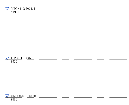
Revit has multiple coordinate systems.  An internal coordinate system and a shared coordinate system.  By default all coordinates, whether they be levels, spot elevations, contour tags, spot coordinates all report the internal coordinate system.  Each of these can be easily changed in their TYPE properties to use shared.  Unfortunately the Nomenclature varies, but the principle is the same:

Level Type Properties: (change "Elevation Base" to shared)


Spot Elevation Type Properties: (change "Elevation Origin" to shared)


Spot Coordinate Type Properties: (change "Coordinate Origin" to Shared)


Contour Label Type Properties: (change "Elevation Base" to Shared)


Best Practice the Internal Coordinates of "Ground Level" should always be 0.

To move the building:

  1. Switch to an Elevation/Section,
  2. On the Manage Tab, Project Location Panel, Position Drop down, Choose "Relocate Project"
  3. The tool works just like the move command, select the base point to move relative to, then the distance and direction you want to move it in (best to only move it vertically in elevation/section).   In this example I'm going to move my levels 6000mm up.
  4. Done, coordinates have been changed, all views are still intact and no cleanup required.  For those who have been doing it some other way.  Please don't do anything irrational.  Think of all the time you can now save...
This method is also better when working with multiple discipline models and the copy/monitor.  If people are using the move command to move their project around it causes everyone grief in this scenario.

Hope this helps.

Tuesday, May 31, 2011

Australia and New Zealand Revit Standards Released (ANZRS)

Want to make top quality content.  The first step would be to download the extensive document pack from ANZRS!  This has been 2 years in the making after being raised at the Revit Technology Conference.

http://anzrs.wordpress.com/

Thursday, July 22, 2010

Why can't I see this element??!

Arggh, there is nothing worse than trying to find why an element isn't visible in a view, so many different potential causes that need to be checked.  I thought I'd put a little bit of a checklist together:

  1. Is the view "Discipline" set correctly?  For example if your view is accidentally or purposelly set to Structural the wall may not be showing because its non-bearing...
  2. Is the view range set correctly to see the particular element?  I'll often switch to my 3D view and orientate it to match the view, if I can't see it in the 3D view its most likely a view range issue.
  3. Is the element in the correct phase and is an appropriate phase filter set in the view to make it visible.  Maybe someone set it in a future phase?
  4. Can you see the element by enabling "Reveal Hidden Elements"?  If so, select it and select unhide element or unhide category.  Try not to use the Override element or hide in view options...
  5. Is the element in a worset that isn't open or turned on in the view?
  6. Is there a filter applied to the view that is causing the element to be hidden?
  7. Has someone used the linework tool on the element?
  8. If its a family, is the detail level of the view set correctly?  Sometimes families are set not to show at Coarse.
  9. If its a family, has someone selected the geometry of the element not to show in plan, section/elevation as the case maybe?
  10. Maybe the view has been created as a detail view?  By default certain categories aren't visible in a detail view...  As such change to a standard section.
  11. Is the element part of a design option and perhaps that isn't the current option for that particular view?
  12. Is there a plan region in the view that is adjust the view range settings incorrectly for the area in question?
  13. If its a datum, is the 3d extents of the datum intersecting the view?
  14. If its a section/elevation marker, check the "hide at scales coarser than" parameter to ensure its set appropriately to show.
  15. Is it part of a linked revit or dwg file?  Ensure that the link is loaded...
I think there are a few more, but that's all i can think of off the top of my head.  Feel free to post comments of any additional ones you think of and I'll add them.

Cheers!

I know this can do my head in sometimes!

Tuesday, May 11, 2010

Revit Hatch Patterns (Hatch Kit)

Firstly apologies for my slackness in regular posts...
This question has come up a lot, and its how do I make custom hatch patterns for Revit?
Typically I'll recommend using Cadro's Hatchkit.

However, I recommend a different workflow to using hatchkit directly as the editor. I like to use the import DXF feature.
  1. Begin by starting up Revit.
  2. Start a new project.
  3. Start a drafting view, set the scale to 1:1 for a drafting pattern or 1:100 or similar for a model pattern.
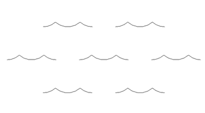
  4. Now using solid detail lines draw the pattern you'd like to create at the scale you require it. In my example I'm trying to create a water surface pattern (some waves).
  5. Next we need to outline a box/tile that if repeated would create a clean pattern and break our linework here.
  6. Then delete the excess linework. (leave the box there as this helps to define the size of the tile)
  7. Export to 2004 DXF format.
  8. Start HatchKit
  9. Go to File-->Import (change files of type to DXF entities) Find you file and import
  10. Now we just need to delete the box that we drew. Select each of them by clicking on the white box and delete. You actually end up deleting 6 lines...
  11. Finally add a name/description/comment then save as a Revit Model or Drafting pattern as required.
  12. Its now ready to be imported and used in Revit!

Wednesday, September 30, 2009

KAUST: Breakwater Beacon Inauguration

After 4 months of documentation and modelling, and finally construction, the Breakwater Beacon is finished.


Designed by Daniel Tobin & Jamie Perrow of Urban Art Projects and the Plaza by Liam Proberts of Fairweather Proberts, Cadway and specifically myself, were given the difficult tasks of taking the complex design and producing accurate and complete documentation in order to realise this design.


Working with the Structural Engineers, Robert Bird Group - Lance Barton, strict construction tolerances were given that were part of the design constraints.


I then took these design constraints and constructed a highly robust Revit Family with over 70 parameters and numerous complex formulas (conditional statements, trigonometry and algebra). By creating parameters and using the API to calculate the true lengths of the edges of the hexagonal rings we were able to automate a lot of the shop drawing creation for the precast concrete elements. Within Revit we were able to directly and automatically extract weights and volumes to supply to the Structural Engineer for calculation.

Unfortunately, it wasn't all straight forward. Early in the design process I had to go through a number of iterations of my family whilst the construction technique was established. That is, which sections were Precast Concrete and which sections with Cast in-situ. The main issue being that the cast in-situ was a different colour to the precast concrete which wasn't a desired architectural outcome.

From there the Lighting Designers, Norman Disney and Young became involved and we worked with them to set out recessed lighting locations directly in the precast pieces themselves and documented their exact locations.

The Structural Engineers calculated 3 lifting points for each piece that simplified the lifting process so the natural centroid of the piece was already correct when lifted by the crane and lowered into position.

From here it was a process of placing all the individual hexagons and adjusting their many parameters to suit the concept design. As we were using Revit, as we placed the elements more and more of the documentation was also being completed. We were given tolerances for the spacing of the pieces to work with and then for every piece we supplied 12 coordinates to locate the precast members onsite (6 vertices internally and externally). Every single piece was different in shape and the internal faces of the precast members were completely faceted so the Revit family had to completely triangulate the faces.

Finally once all these pieces were placed, we then had to specifically model up the 4 different entrance frames which also had a steel framed core. We supplied the centroid points of the void spaces to the structural engineer and produced shop drawings for the many segments that then framed the doorways.


The final stage to be completed is the entire plaza level which should now be well underconstruction to immitate the Giants Causeway.

If anyone has any questions please don't hesitate to post a comment. I hope some find this information useful or interesting.

Thursday, July 10, 2008

Revit Rendering Fundamentals

Here is a link to the other presentation I did:

Apologies this file is rather large due to all the embedded images (37MB approx.)

Again, I love to hear feedback both good and bad. It gives me incentive to keep updating this page...

EDIT: Webserver no longer allows me to have files this large. Please see link to PDF.