Xrev API Tools: Increase Productivity!

Feeds

Loading...

Thursday, March 22, 2012

New Laptop & Nasty Revit Bug

With starting my new company I decided to splash out and get myself a decent laptop.  I decided on a new Dell XPS15 with 256GB SSD.

Its a great computer, extremely fast and great battery life.  My main issue occurs in Revit:

Every time I'm in Revit and I have a child window open in Revit, for example the family types dialog, every 20-30 seconds the window loses focus and the Revit main window has focus! I can be typing away in one of the fields and all of a sudden I've committed another command in the background parent window (like opening the visibility/graphics dialog).  Almost like the dialogs in Revit are modeless!

As you can probably imagine this can be extremely frustrating and counter productive when you have to constantly have to reselect the child window to have focus so you can keep working.  Especially when you are writing long formulas that you have to scroll across the window to get to the end of the formula.  Then by the time you've scrolled across the window loses focus and you have to do it again!!!

This issue from my experience only occurs in Revit.  I obviously checked all the obvious things like touching the trackpad, or bumping a key - but my hands can be in the air well away from the laptop and it still does it. As such I filed it with Autodesk Support.

Of course they first asked the obvious questions, are you running the latest build, do you have Autodesk Certified drivers (and the autodesk certified drivers are years old!), etc.  I ensured I had tested all their suggestions and none of which resolved the issue.  It has now been escalated to development and apparently I'm not alone in the this issue, which is slightly re-assuring as that may mean there is a fix planned...

Anyway, I thought I would share just in case others are experiencing this issue and looking online for a solution.

Monday, February 13, 2012

Revit Bird project completed

I thought those that were interested might like to see the completed project of the bird I did all the laser cut files for.

http://uapmarker.com.au/blog/james-eleanor-avery-with-uap-studio-lucky-dip-the-darling-hotel-sydney/

Wednesday, January 25, 2012

Chris Price & Xrev - Consulting

Hello All,

I thought I'd let my readers know that I am now consulting my services in the Revit Architecture, Structure, Navisworks, BIM space. (commencing 13th February 2012)

If you require Revit Implementation, in-house Revit Training, Revit Training Classes, Revit Management, On Project Revit Support, Revit Start-up Assistance, upskilling intermediate & advanced Revit users, Revit Collaboration, IPD and everything Building Information Modelling.

Please don't hesitate to email me at Support at Xrev dot com dot au. I can supply you with my costing and schedule availability!

I have experience with:

  • Multi-discipline collaboration
  • Revit Asset Management
  • Revit Facilities Management
  • Revit Digital Fabrication (laser cutting, CNC, etc)
  • 4D Sequencing
  • Extracting Quantities & Weights from the model
  • Various Energy Analysis
  • Cost Estimation from the model
  • Clash Detection
  • BIM Specifications
  • Integrated Project Delivery
  • Training large groups/presenting

Tuesday, January 03, 2012

Laser Cut files & Fabrication from Revit


Now that it is no longer under NDA, I'd show off a quick project that I recently completed for a client where we were asked to produce laser cut files for all the steelwork.

Thankfully I had a copy of Revit 2012 pre-release to play around with which just happened to add a new feature that allows me to create face based void families or nest voids in families and have them cut other families in the project beyond just system families such as walls/floors/roofs etc.  (love it when Autodesk release a feature that I can use straight away)

Using Structural framing, and structural columns I was able to quickly generate all the members to their accurate sizes.  The difficulty was that each of the 3 layers of 40x16mm RHS channels that make up the infill actually need to penetrate the external channels.  Of course the laser cut machine can only cut penetrations perpendicular, so this complicated things.  As such I generated a face based void family with instance parameters to control its lengths and radius corners.  I placed all 1340 instances of these and flexed their lengths to suit the required opening for each of the intersecting members based upon their angle of incidence and ensured no members intersected each other.

I then had our developer create a macro command using VSTA to isolate each member, create a 3D view of only that member and then export out a .SAT file and .DXF file for the laser cutting service.

I was also asked to advise the weight of this structure. Easily done through some schedules to pull out the volume of steel and a calculated parameter based upon the mass of steel being 7850kg/m³ this was all able to be automated.

Lessons learnt: I found a few bugs in this tool where the face based voids families would cut certain structural columns, which have now been addressed in the released version.  I managed to source the issue and devise a workaround. I had planned to make this much more complicated to facilitate change, but I opted for the manpower approach as I thought it was resolved.  Unfortunately for me, there were a couple of design iterations which we somewhat painful to redo.  Had I have known these were coming I would have made the mesh members and penetrations parametric.

NEXT PROJECT for the same client:
A 4.5 metre Bird made from aluminium sheet with a polystyrene core to be suspended in the foyer.

Requirements:
  • An IGS file for the CNC router to cut the polystyrene blocking to shape.
  • Fully nested cut files for all the aluminium sheet
  • Structural Steel Cut files for the support frame
  • An overall weight of the bird

Challenge accepted!

We were supplied with a model created in 3DS Max. My first thought was great, I'll use the unfolding tools of Autodesk Inventor to make light work of this.  This way I could build in K factors etc.  But of course Inventor doesn't handle geometry created by other applications well at all.  I didn't feel in the mood to remodel the complicated form from scratch in Inventor so instead I looked to Revit. Unfortunately there was some issues in the nurbs translation and the import into Revit - which I didn't discover straight away.  As you may know a nurbs face can only have 3 or 4 sides.  When importing into Revit the surface was being triangulated.  Some of the planar faces on this bird had as much as 12 sides.  Working with the designer in 3DS Max we managed to sort out a workflow that gave me the best possible base to work from.  We even explored tidying up the bird directly in Revit, so we create a tool using the API that was able to automatically convert the import into native Revit Reference Lines, Points and forms.  We didn't end up using it, but I'm sure it will come in handy in the future.  We may even make it publicly available if we get the time to make it robust to everyone elses different scenarios.

I imported this form into the Revit Conceptual Massing environment and created a family for it.  I then loaded it into a new project and used the curtain panel by face tool (using a special Aluminium system panel type that I made), selected all the faces and generated the curtain system.

Great, I now had a panelised system for all the pieces.  I then manually merged some of the complicated pieces so we didn't end up with tiny little slithers to be assembled.  Next step, systematically number all the panels (434) with unique marks, we didn't automate this so it was somewhat tedious.

Again we looked to the API to create a macro that automatically created an isolated 3D view for each curtain panel orientated to look perpendicular to the surface.  Easy enough, but how do we no which side of the surface we are looking at.  The edges of each panel needed to be bevelled at 45° so this was important.  Unfortunately there seemed to be no real logic between what side revit determined the interior or exterior of the panel even though they were all part of the same system, they weren't necessarily orientated the same way.  We were able to get around this through Raytracing in the API, which aided us in determining the interior and exterior face.  We re-ran the macro and now we had an exterior view of every panel isolated in the model.

Next step, exporting the views:
As you may or may not know, if you export from a 3D view you get a 3D file.  In this instance we needed 2D Cut files.  How do you get a 3D view to export as 2D?  You place it on a sheet.  We configured the macro to then place all 434 views on a single sheet, then exported (DXF) the sheet and left the "Xref views on sheet" option checked so we would get separate files for each of the files.  Of course we had no control over the naming of these Xref's so we then had to use a small utility to systematically rename all the files so they corresponded to their Mark.

Finally to create the nested cut files, we used another commercially available utility where you can simply enter the sheet sizes, specify the individual cut files and it automatically nests the pieces and optimises them as well as tagging them.

The last task was to generate the 3D cut files for all the structural steelwork.

Wednesday, November 30, 2011

Xrev - Trial Survey Competition Results

Results of a recently conducted survey on the Revit Add-in Xrev Transmit - designed for issuing Revit sheets to PDF, DWG, DWF etc with automatic naming and filing, including a drawing register/transmittal.


What people are saying:


"We have users who want to marry you they are so happy with the time savings"
"Excellent product - I couldn't Revit without it"
"The time savings are great.  Everyone loves using it."
"We absolutely love the product.  It has exceeded our expectations and is a pleasure to use"
"Xrev Transmit makes tasks that have always been tedious, fast and dare I say it enjoyable"

Friday, November 11, 2011

Easily changing building levels

I'm always amazed when people don't know about this very easy process of changing a building's Levels to reflect the actual RL's of the site.

All to often people tell me how they go through the tedious process of selecting all their levels and using the move command, then have to select all their views/details/text etc and move it all up or down to align with the new location.

Are you crazy!!  Never do this!

Revit has multiple coordinate systems.  An internal coordinate system and a shared coordinate system.  By default all coordinates, whether they be levels, spot elevations, contour tags, spot coordinates all report the internal coordinate system.  Each of these can be easily changed in their TYPE properties to use shared.  Unfortunately the Nomenclature varies, but the principle is the same:

Level Type Properties: (change "Elevation Base" to shared)


Spot Elevation Type Properties: (change "Elevation Origin" to shared)


Spot Coordinate Type Properties: (change "Coordinate Origin" to Shared)


Contour Label Type Properties: (change "Elevation Base" to Shared)


Best Practice the Internal Coordinates of "Ground Level" should always be 0.

To move the building:

  1. Switch to an Elevation/Section,
  2. On the Manage Tab, Project Location Panel, Position Drop down, Choose "Relocate Project"
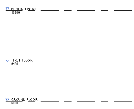
  3. The tool works just like the move command, select the base point to move relative to, then the distance and direction you want to move it in (best to only move it vertically in elevation/section).   In this example I'm going to move my levels 6000mm up.
  4. Done, coordinates have been changed, all views are still intact and no cleanup required.  For those who have been doing it some other way.  Please don't do anything irrational.  Think of all the time you can now save...
This method is also better when working with multiple discipline models and the copy/monitor.  If people are using the move command to move their project around it causes everyone grief in this scenario.

Hope this helps.

Tuesday, September 27, 2011

But my structural slab isn't flat!

Set downs in structural slabs or falls to slabs can be tricky to achieve.  Below are some of the methods I used to make things simpler:

  • The first question you need to ask is do I need a thickening where the recess is? If so, then the correct approach would be to simply model another floor with the required negative level offset and overlap the floors. Then provided the floors are of the same materials and both have the same structural property then you can simply use the Join Geometry tool to clean them up.

  • However, if you don’t need a thickening Revit 2012 allows you the ability to create families with Voids that can cut multiple elements in the project: 
    1. Create a new Generic Model family - I like to use face based; 
    2. Add reference planes to control its length and width by instance, and its depth by type. 
    3. Then add a void and constrain it to the reference planes. 
    4. Now ensure you check the option “Cut when nested”. 
    5. Finally create an initial type for a standard set down depth. 
    6. Then just load into your project, place where needed and drag the grips to make it the appropriate size.
    7. Then use the Cut geometry tool, select the floor you wish to cut and then the generic model family to have it cut the floor. You can even have it cut structural beams and multiple floors.

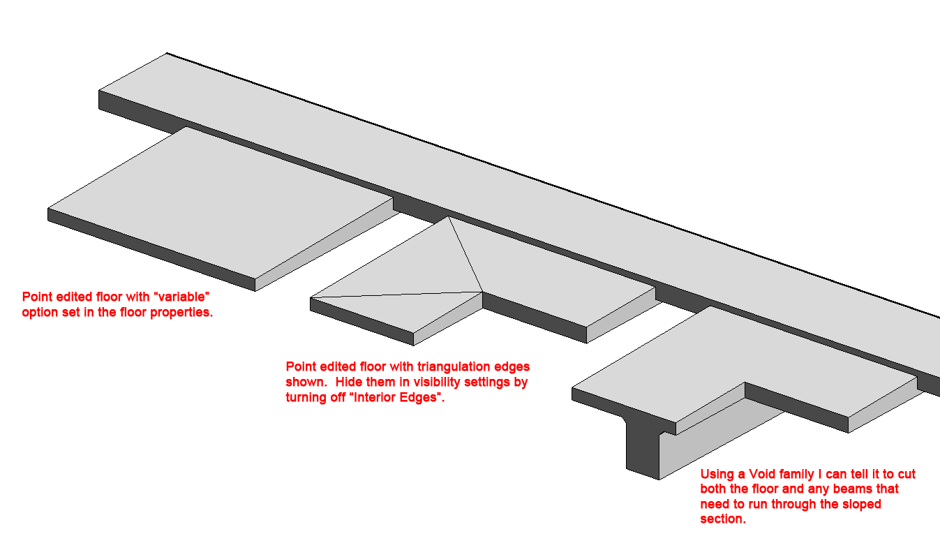
  • For balconies with structural falls to the top face only you can use the point editing tools to drop edges/points lower to create the falls and ensure the layer of the floor is set to be “variable” in its properties. However, if the balcony isn’t rectangular, may be it is L shaped, then this approach can result in all sorts of triangulation edges – this can be worked around by turning off “interior edges” in the visibility settings. But you could also produce a similar generic model family for falls (using a void blend). This way the fall could also cut structural beams as well!

Friday, July 29, 2011

Revit 2012 - AS1428.1-2009 Door Circulation Checker

Hi Everyone,

Sorry I still haven't posted the video and datasets from RTC2011, I will do it when I get a spare few hours, need the incentive to sit down and record it all!

In the meantime I thought I'd share a little freebie, especially useful for all Australian users.  I have compiled a detail component family to graphically represent disabled circulation requirements as per AS1428.1-2009 to match Figure 31.  It has been setup to be completely fool proof, that is if you set any values that don't comply to this standard, you will get a nice large warning advising that the door doesn't comply.

It has some pretty darn long nested conditional statements (each about half a page of single line text) to match the requirements.  To help manage such long formulas I used an Excel spreadsheet to compile the formulas directly from the table.

Hope all find this useful.  Please let me know if you do as it may give me incentive to post some more...

Technically you could nest this family directly into your doors and use some formulas to to have it set to the appropriate sizes.  However, you may find that when you flip your door it will flip around the centre of the extents of the family and not about its origin.  A really annoying limitation of Revit that drives me nuts!!

Door Circulation Family.
Download it here and the Type Catalogue of standard sizes here.

Saturday, June 25, 2011

RTC USA - Conference Materials

As some of you may know myself and many other Reviteers are currently attending and speaking at the Revit Technology Conference in Huntington Beach, California.

For those attending the sessions I will post links to the course materials, including presentation and datasets when I return to Australia.  These materials will also be available for download from the RTC ftp site.  Access details are typically emailed out to attendees with a couple of weeks of the conference completion...

Hope all attending are getting a lot of information out of it.  I've picked up a few little things that I've missed in the recent version - as such it is a very worthwhile trip.  Hope more people show interest next year and make this event a regular mark on your calendar!

Cheers,
Chris Price
aka Mr Spot :)

Tuesday, May 31, 2011

Australia and New Zealand Revit Standards Released (ANZRS)

Want to make top quality content.  The first step would be to download the extensive document pack from ANZRS!  This has been 2 years in the making after being raised at the Revit Technology Conference.

http://anzrs.wordpress.com/

Wednesday, May 04, 2011

Revit 2012 Viewer Mode

Did you know that in the Revit 2012 suite there is now a special "Viewer" mode.  I only discovered this the other day.

Finally a reliable, built in method (without having to rely on demo modes) to enable the Principals, Engineers, or Revit Illiterate Architects access to a Revit model that they can't destroy.

With the viewer it allows all standard functionality but:


  • You can't save or save as,
  • Export or publish views/models if you make any changes,
  • Print if you make any changes,
Still need to test out how this behaves in a worksetted file.  Can anyone comment on whether it borrows elements and automatically relinquishes them upon closing, or something similar?

Revit 2012 & Nested Structural Columns Workarounds

If you've ever tried to nest structural columns or structural framing members and made them shared so you can tag the members independently of the host family, then there is a good chance you've come across this issue.  That is the column height or beam length defaults to its original size and ignores its constraints set by the host family.  Find out how to work around this.

Sunday, April 17, 2011

Revit Technology Conference USA & Australia - June / May

For those of you that I interested I'll be running 3 classes at the above events.


  1. Architectural Advanced Families (LAB)
  2. Structural Advanced Families (LAB)
  3. One Model (Revit Server, Worksharing API, Bluestreak, Security - Is it possible yet?)
I was really hoping to have the content of the Labs be directly based from the attendees requests.  However, so far the response has been far from overwhelming.  Especially considering that the Labs at the Australian event are sold out and wouldn't be surprised if the USA event isn't too far behind...

I'd really like the attendees to feel as though they've not only learnt something at the lab, but also to go away with something useful in terms of family content that they can use in their firms...

I plan on writing the 5 or so hours of training content over the Easter break so if you do have some suggestions please post your comments below!!  Remember, this is advanced some I'm going to touch some tricky topics including:
  • Referencing Parameters
  • Nesting
  • Arrays
  • Adaptive Components (depending on the suggestions)
  • Family Type parameters
  • Formulas (Conditional, Mathematical, Rounding, Trig etc.)
  • Type Catalogues
  • Shared Families
  • Nested Detail Components
  • Detail Level Control
  • Best Practice
  • Reference Planes / Lines / Points
I'm still contemplating whether I take the approach of setting up a bunch of half complete families and then we just tackle the tricky parts, or whether we go through the entire process of creating an advanced family from start to finish?

Otherwise I'll just pick some complicated stuff at random and hope that the bulk of people find the content useful.

BTW, I also believe that the Australian & New Zealand Revit Standards (ANZRS) for family creation are going to be released at this years event.  I've reviewed it and it is an excellent set of guidelines for creating families that will work with all disciplines and standardise online content if adopted by Autodesk Seek as well...

Thursday, December 16, 2010

Roombook Extension for Revit 2011 Available

There is a new extension available from the Autodesk Subscription Centre website for particular locations.  The extension was originally developed for the German market, but has now been modified for wider international use.

Below is some information off the subscription site:


  • The program calculates the surfaces of walls, floors and ceilings as well as room circumference and furnishing elements on a per-room basis and in total. 
  • The calculation of each surface is made transparent by detailed listing of all sub areas. 
  • Apart from automatic detection of elements and sub areas, it is also possible to add further elements manually. Additionally, it is possible to illustrate situations with no constructive equivalent in the project, by numerical definition or graphical selection of detail or model lines (use case: tile panels). It is also possible to define a wall height reduction on a per-room basis, in order to calculate the material requirements in case of reflected ceilings. 
  • All sub areas can be modified manually, including materials. This allows to handle exceptions to the rule and special situations. 
  • Surface material types contain material definitions for walls, slabs, ceilings and room circumference, which are typically assigned to particular rooms (Example: Bathroom, Habitable Room Carpet etc.) This allows to assign surface materials to rooms with one click. 
  • The calculated quantities can be exported in a clear and detailed Excel form, separated in 
  1. Wall surfaces (including inner reveals, and window area per room in the Excel survey) 
  2. Floor surfaces (including threshold areas)
  3. Ceiling surfaces
  4. Room circumference 
  5. Furnishing elements and a survey which lists face to face all quantities per room and in total. 
  • Material requirements are listed per room and in total.  
  • Additionally is supported the export to a dwf-file which later can be opened and edited further in Autodesk Quantity Takeoff (QTO), as well as a CSV output


Find out more here:
Autodesk Subscription Centre

Friday, November 05, 2010

Collaborative Modeling with Revit Worksharing and Bluestreak

For those needing to communicate between offices and work on single models. Use Revit server coupled with Autodesk Bluestreak.

Now all we need is a multi-discipline solution to control those pesky architects moving structural elements or vice versa. (we've got one in the works...)


Saturday, October 09, 2010

Xrev Revit API Tools

Great News!

Our new Xrev website goes live next week.

www.xrev.com.au

it will also be accessible from www.cadway.com.au

Checkout Xrev Transmit! Our Revit issuing tool to take the pain out of issuing drawings whether it be hard copies, digital copies or both, as well as managing your transmittals... LEVERAGE ALL THAT INFORMATION IN YOUR REVIT MODEL for generating the transmittal rather than having to reproduce it in your file names and transmittal documents...

Soon to follow are:

Xrev Sheets
Xrev Transmit PRO

Making a completely parametric mobile crane - Final

Hi Everyone,

Again, sincere apologies for the delay in updates.  Please watch the below 3 videos for the final explanation of how I went about making this family.  Comments always welcome and any recommendations for what people what me to show next.

Cheers.


Thursday, September 30, 2010

Revit 2011 - Subscription Advantage Pack Released

If you haven't already, download the Revit 2011 Subscription Advantage Pack to get Revit Model Server & Conceptual Energy Analysis tools.


Finally a tool for teams that are spread across multiple offices...

NOTE: You must have a valid Subscription to do this and be logged into the Autodesk Subscription Centre.

http://subscription.autodesk.com/

Thursday, July 22, 2010

Revit 2011 - Creating a Parametric Shade Sail using Adaptive Components

In this video I'll demonstrate how something can be easily made very parametric using adaptive components for a tension structure such as a shade sail.

Why can't I see this element??!

Arggh, there is nothing worse than trying to find why an element isn't visible in a view, so many different potential causes that need to be checked.  I thought I'd put a little bit of a checklist together:

  1. Is the view "Discipline" set correctly?  For example if your view is accidentally or purposelly set to Structural the wall may not be showing because its non-bearing...
  2. Is the view range set correctly to see the particular element?  I'll often switch to my 3D view and orientate it to match the view, if I can't see it in the 3D view its most likely a view range issue.
  3. Is the element in the correct phase and is an appropriate phase filter set in the view to make it visible.  Maybe someone set it in a future phase?
  4. Can you see the element by enabling "Reveal Hidden Elements"?  If so, select it and select unhide element or unhide category.  Try not to use the Override element or hide in view options...
  5. Is the element in a worset that isn't open or turned on in the view?
  6. Is there a filter applied to the view that is causing the element to be hidden?
  7. Has someone used the linework tool on the element?
  8. If its a family, is the detail level of the view set correctly?  Sometimes families are set not to show at Coarse.
  9. If its a family, has someone selected the geometry of the element not to show in plan, section/elevation as the case maybe?
  10. Maybe the view has been created as a detail view?  By default certain categories aren't visible in a detail view...  As such change to a standard section.
  11. Is the element part of a design option and perhaps that isn't the current option for that particular view?
  12. Is there a plan region in the view that is adjust the view range settings incorrectly for the area in question?
  13. If its a datum, is the 3d extents of the datum intersecting the view?
  14. If its a section/elevation marker, check the "hide at scales coarser than" parameter to ensure its set appropriately to show.
  15. Is it part of a linked revit or dwg file?  Ensure that the link is loaded...
I think there are a few more, but that's all i can think of off the top of my head.  Feel free to post comments of any additional ones you think of and I'll add them.

Cheers!

I know this can do my head in sometimes!