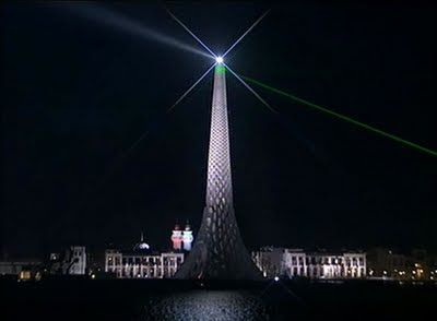
Designed by Daniel Tobin & Jamie Perrow of Urban Art Projects and the Plaza by Liam Proberts of Fairweather Proberts, Cadway and specifically myself, were given the difficult tasks of taking the complex design and producing accurate and complete documentation in order to realise this design.
Working with the Structural Engineers, Robert Bird Group - Lance Barton, strict construction tolerances were given that were part of the design constraints.
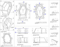
I then took these design constraints and constructed a highly robust Revit Family with over 70 parameters and numerous complex formulas (conditional statements, trigonometry and algebra). By creating parameters and using the API to calculate the true lengths of the edges of the hexagonal rings we were able to automate a lot of the shop drawing creation for the precast concrete elements. Within Revit we were able to directly and automatically extract weights and volumes to supply to the Structural Engineer for calculation.
Unfortunately, it wasn't all straight forward. Early in the design process I had to go through a number of iterations of my family whilst the construction technique was established. That is, which sections were Precast Concrete and which sections with Cast in-situ. The main issue being that the cast in-situ was a different colour to the precast concrete which wasn't a desired architectural outcome.
From there the Lighting Designers, Norman Disney and Young became involved and we worked with them to set out recessed lighting locations directly in the precast pieces themselves and documented their exact locations.
The Structural Engineers calculated 3 lifting points for each piece that simplified the lifting process so the natural centroid of the piece was already correct when lifted by the crane and lowered into position.
From here it was a process of placing all the individual hexagons and adjusting their many parameters to suit the concept design. As we were using Revit, as we placed the elements more and more of the documentation was also being completed. We were given tolerances for the spacing of the pieces to work with and then for every piece we supplied 12 coordinates to locate the precast members onsite (6 vertices internally and externally). Every single piece was different in shape and the internal faces of the precast members were completely faceted so the Revit family had to completely triangulate the faces.
Finally once all these pieces were placed, we then had to specifically model up the 4 different entrance frames which also had a steel framed core. We supplied the centroid points of the void spaces to the structural engineer and produced shop drawings for the many segments that then framed the doorways.
.jpg) The final stage to be completed is the entire plaza level which should now be well underconstruction to immitate the Giants Causeway.
The final stage to be completed is the entire plaza level which should now be well underconstruction to immitate the Giants Causeway.If anyone has any questions please don't hesitate to post a comment. I hope some find this information useful or interesting.
22 comments:
Wow. Very impressive stuff! Did you use the API for mainly scheduling? You mentioned placing each piece. Did you insert each instance and adjust parameters or was it a curtain panel system? What sort of family was it?
Nice! did you document each panel in a seperate file or did you isolate each one in the main project file?
The API was used to generate the shop drawings (created views, applied values to a 2D detail component of each of the individual faces based on the values of the 3D objects).
This was done in Revit 2009, so the curtain panelling system wasn't yet available. Each piece was placed and then adjust to suit. Due the randomness though the new patterning tools are still not able to create the random lower section however they could be used to do the more regular upper sections.
It was all documented in a single file with each element isolated using filters.
chris, that is mighty fine work.
i guess you are well past wrangling with stairs and rails then?
seeing what you have done , and the description of what you did toi achieve it, im giving up immediately.
guess im still stuck in the 2d world.
great work though.
I was wondering if this could be done any easier with 2010? I think this is definitely an advantage of using Revit. It beats Autocad for sure. I am still trying to understand the whole concept.
Do you have more pictures from different views?
Very cool!
The upper sections could, but the first 23metres would still need to be done the same way as its too random...
I have hundreds of pictures, when I get the official marketing images from the client I will probably post some more...
Construction has been rushed and now a big cleanup is required...
Very impressive and inspirational work... both architecturally and as an example of what Revit can do.
What are the chances that you'd be able to share with us a version of the family (or project)? I'd love to reverse engineer this... maybe learn something about the API along the way (don't even know where to start with this).
Great work. Keep it up!
Great work, but with all due respect, a structure like that could have been easily done in Digital Projects, Generative Components or even Grasshopper. I just hope Autodesk is aware of the limitations within Revit.
Actually, those products were explored. The form was too random to be simply generated by algorithm ala Grasshopper or GC. Whilst Revit has limitations it was certainly up to the task for creating this form and the documentation when pushed.
The conceptual modelling tools in Revit are a big step forward, but until you can manually edit each of the vertices of the curtain panel patterns and extract automated shop drawings from the panels it doesn't really have a documentation connection...
I would love to see someone produce this same model with all the structural design constraints in another software and still be able to produce useable automated documentation that is guaranteed to be 100% accurate. I'm all keen to learn other software but couldn't see any benefits in trying something different on this when it worked fine...?
Hi Chris!
I've recently started my own blog. It's very new and much of it is a work in progress.
I have added your blog to my blogroll, but I wanted to give you the opportunity to inform me if you'd rather I not provide the link.
Anthony Mason
http://dailyoccurrence.wordpress.com/
Very impressive! I can't even imagine modeling such an interesting structure, let alone documenting it.
Congratulations on a very fine piece of work. I would love to see more photos / renderings.
Did you have to model each piece or did you parameters do most of the work for you? I would love to see a sample of one of the families you created to create this masterpiece.
Did you have to model each piece or did you parameters do most of the work for you? I would love to see a sample of one of the families you created to create this masterpiece.
There were basically one family, however there were a couple of special pieces.
Hexagon - Standard (most of them were this type)
Hexagon - Footings
Pentagon - Standard
Pentagon - Footings
Tetragon - Standard
Tetragon - Footings
Then the large doorway frames were done in-place as each of those were quite different and quite complicated in their form.
Chris, love your work. Us CG people at UAP always enjoyed using your models in Rhino and 3ds Max. That game engine based walkthrough of the Beacon and surrounding area was fantastic.
Congratulations! on your acheivements with this tremendous example of innovating use of Parametrics.
I would be grateful if you would identify 'learning' material sources that you used in your development, and skillset reqrmts ie. level of programming capability, languages, etc.
Many thanks.
Hey Mike,
Mathematics - Just remembering stuff from school, didn't really refer to anything in particular.
Advanced Family Creation - self taught, there was a lot of trial & error though as Revit wasn't the most predictive in terms of what methods to achieve the forms it would allow. Some seemed like they "should" work but didn't. Methods such as using Voids purely as a framework to constrain other geometry to, using reference lines on varying planes and blends. Using shared parameters instance/type. Creating Detail Components for the faces using the same shared parameters.
Programming - Used GuyR's blog and the factory blog as well as the SDK.
Just wondering why there is never any mention of AI3D in this whole post.. Considering the model was made from scratch at AI3D in 3DS max and the company I'm working for did the Realtime 3D work on it too. There was no way this project was getting off the ground without us. WOW.. Even someone from UAP saying someone else did the Realtime animation?? Fine, we didn't document it... but there would not have been anything to document without us making it in the first place. I have not seen a single site about the beacon where we get any mention at all(including UAP's site).. I mean we only built the model that everything is based off right? Love to see anyone else make this model.. or have the flexibility we allowed UAP to have over the design.
Troy Pinkerton
working for AI3D
Troy,
I totally understand where you are coming from. But I think you'll find my post is more about the documentation methodology and converting the design into something that could actually be built.
If you don't feel like you are getting the recognition you deserve for this project, do some of your own marketing on it like we have...
Chris, Impressive stuff!
A couple questions...
1- How are you reporting the coordinates of the corners with all 3 (xyz) values?
2- curious about your families, the throat looks to be a simple blend. but how about the base? I'm not sure how I would go about doing that, A floor would work (in the project environment) with varying corner heights but I can't figure how to do it in a family environment. Any advice? Thanks
JB
Sorry Chris,
I should have left my email in case you didn't want to post any of these on your blog.
You can email me at justinsblack@gmail.com
Thanks
There were 12 coordinates supplied for each piece (interior and exterior faces), supplied via spot coordinates.
The families consisted of blends stacked on faces of other blends and I also used a void that didn't cut anything as a parametric framework to define faces that I didn't have...
Post a Comment